Sound and Vibration Instrument Hire and Calibration
Bruel & Kjaer 2238 Specifications
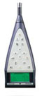
| B&K 2238E : Mediator - Sound Level Meter - Class 1 |
|---|
All our 2238 Sound Level Meters include the following modules
BZ 7126 - Basic Sound Level Meter SoftwareBZ 7125 - Enhanced SLM Software
BZ 7124 - Logging Sound Level Meter Software
BZ 7123 - Frequency Analysis Software
Common Specifications - all 2238 Mediator versions:
BS EN 61672 - class 1
BS EN 60651 - class 1
BS EN 60804 - class 1
Nominal Sensitivity : -30 dB re 1 V/Pa or 31.6 mV/Pa
Frequency Range : 8 Hz to 16 kHz ± 2 dB
Capacitance : 12 pF at 250 Hz
Extension Cable : 3 m included. No re-calibration is required
Dynamic Range : 80 dB adjustable to give full scale readings from 80 dB to 140 dB in 10 dB steps
Max. Peak Level : 3 dB above full scale reading
Upper RMS Limit for Crest Factor = 10 : 17 dB below full scale reading
Pulse Range : 83 dB
Linear operating ranges - broadband : For the individual level ranges, at 1 kHz, the nominal upper boundary level minus the lowest sound pressure level measurable with a noise margin of 5 dB and with a Type 4188 microphone of nominal sensitivity;
| Upper Limit | Lower Limit | Max peak | Upper limit CF = 10 |
|---|---|---|---|
| 140 dB | 60 dB | 143 dB | 123 dB |
| 130 dB | 50 dB | 133 dB | 113 dB |
| 120 dB | 40 dB | 123 dB | 103 dB |
| 110 dB | 30 dB | 113 dB | 93 dB |
| 100 dB | 25 dB | 103 dB | 83 dB |
| 90 dB | 25 dB | 93 dB | 73 dB |
| 80 dB | 25 dB | 83 dB | 63 dB |
This is due to the combination of electrical noise and microphone thermal noise at 20 °C (68 °F).
Typical values with supplied microphone of nominal sensitivity - in dB.
| Weighting | Meter | Microphone | Total |
|---|---|---|---|
| A | 14 dB | 14.2 dB | 17.1 |
| C | 17 dB | 13.2 dB | 18.5 dB |
| Lin. 5Hz - 20 kHz | 22 dB | 14.5 dB | 22.7 dB |
129 pixel x 64 pixel dot matrix display with back light
Mediator supports a total of four timers which allow setup of measurement start times up to a month in advance
Semi-automatic using and external Sound Level Calibrator
The initial factory calibration, sensitivity and microphone serial number is stored for comparison with later calibrations. when using the supplied microphone the maximum allowed deviation from the initial sensitivity is ± 1.5 dB. An unspecified microphone can be chosen during calibration, in which case calibration can be made with practically any sensitivity.
Stored Calibration History : 20 latest calibrations plus initial calibration.
2 Mbytes. Up to 511 measurements can be stored by each loaded software module, including time stamp, complete setup and calibration data
Semi-automatic using and Real-time - calendar
Conforms to EIA/TIA 574 - RS-232, coupled as data terminal equipment, DTE.
Connector : D-type male 9-pin
Baud Rates : 4800 to 115200
Word Length : 8 bits, no parity, 1 stop bit
Handshake : hardwired, modem
From power on < 10 s
Storage Temperature : -25 to +70 °C (-13 to +158 °F)
Operating Temperature : -10 to +50 °C (14 to +122 °F)
Effect of Temperature : < 0.5 dB (-10 to +50 °C)
Effect of Humidity : < 0.5 dB for 30% < RH < 90% - at 40 °C, 1 kHz
Four 1.5 V Lr6/AA alkaline cells
Lifetime at room temperature : Typically > 10 h and with filter set selected typically > 7 h
Voltage : Regulated 7 to 15 V
Power : Approximately 150 mA at 7 V and with filter set selected 210 mA
Weight : 460g (1 lb 2 oz) with batteries
Dimensions : 257 x 97 x 41 mm
Simultaneous detection of spectrum and broadband parameters
Spectrum : 1/1 octave and 1/3 octave band filters with two exponential time weightings - Fast, Slow - and a linear averaging detector
Broadband : Two selectable exponential time weightings - Fast, Slow - and a linear averaging detector
Selectable frequency weighting : A, C or Lin
Overload Detector : Monitors all the frequency weighted channels
Spectrum : Bar graph display of current and averaged spectrum with cursor read-out plus broadband channel Leq, Lmin and Lmax can be selected for graphic display and read-out
Broadband Measurement : Range and quasi-analogue bar, plus four measurement parameters that can be freely selected from all available parameters during measurements
Time/accuracy optimised scan time at three confident levels, 0.25, 0.5 or 1.0 dB, or manually selected dwell time in the range 1 s to 1 h
User selected number of scans, in the range 1 - 99, averaged into one resulting spectrum
Connector : Lemo coaxial
AC Output Signal : Range adjusted AC output, filtered through the currently selected band - short circuit protected
Output : 1 Vrms corresponds to full scale indication
Max. Load : 10 kΩ // 1 nF
Output Impedance : Typically 100 Ω
Connector : Lemo coaxial
DC Output Signal : DC version of the signal on the RMS detector, delayed 0.8 s - Fast, Inst., short circuit protected
Output : 0 to 4.0 VDC, 50 mV/dB
Max. Load : 10 kΩ // 1 nF
Output Impedance : Typically 100 Ω
Conforms to the following :
IEC/EN 61260 - 1995 - Octave and 1/3 Octave bands Class 1
Nominal 1/1 Octave Band Centre Frequencies : 31.5 Hz, 63 Hz, 125 Hz, 250 Hz, 1 kHz, 2 kHz, 4 kHz and 8 kHz
Nominal 1/3 Octave Band Centre Frequencies : 20 Hz, 25 Hz, 31.5 Hz, 40 Hz, 50 Hz, 63 Hz, 80 Hz, 100 Hz, 125 Hz, 160 Hz, 200 Hz, 250 Hz, 315 Hz, 400 Hz, 500 Hz, 630 Hz, 800 Hz, 1 kHz, 1.25 kHz, 1.6 kHz, 2 kHz, 2.5 kHz, 3.15 kHz, 4 kHz, 5 kHz, 6.3 kHz, 8 kHz, 10 kHz and 12.5 kHz
| Leq | LZmax | LZmin |
| LXZp | LXZInst | LXZmax |
| LXZmin | LXeq | Loverload% |
| Under range% | Elapsed Time | Start time |
| Start date | Time |
X = Frequency weighting A, C or L
Z = Time weighting F or S
Detectors :
Two detectors with independent frequency weightings. one detector is an RMS detector and the other can be set up as a Peak detector or an additional RMS detector, allowing two independently weighted RMS detectors in parallel, each providing three exponential time weightings in parallel.
Overload Detector: Monitors all the frequency weighted channels
Exchange Rate : 3 dB - in addition 4 or 5 dB can be selected
Measurement Display, current log period : Range and quasi-analogue bar, plus four measurement parameters that can be freely selected from all available parameters during measurements.
Manual control, or pre-set measurement time with automatic storage of measurements
Connector : 2 pin Lemo. Can be used as an AC output or a DC input for an external signal
AC Output Signal : Range adjusted AC output, unweighted or with the frequency weighting selected on the RMS detector 1 - short circuit protected
Output : 1 Vrms corresponds to full scale indication
Max. Load : 10 kΩ // 1 nF
Output Impedance : Typically 100 Ω
DC Input :
Voltage Range : 0 to 4 V, max. -1 to 6 V
Resolution : 5 mV, 800 steps
Connector : Lemo coaxial, can be used as a DC output, a DC input for an external signal, a trigger input or a trigger output
DC Output Signal : DC version of the signal on the RMS detector 1, delayed 0.8 s - Fast, Inst., short circuit protected
Output : 0 to 4.0 VDC, 50 mV/dB
Update Rate : 160 times a second
Max. Load : 10 kΩ // 1 nF
Output Impedance : Typically 100 Ω
DC Input :
Voltage Range : 0 to 4 V, max. -1 to 6 V
Resolution : 5 mV, 800 steps
Trigger Input :
Voltage Range : 0 to 4 V, max. -1 to 6 V
Trigger Level : 2 V, duration > 12.5 ms
Trigger Output :
Level : 4 V
Duration : Throughout measurements
| LXYmax | LXYmin | LXTN |
| LXeq | LXIeq | LAFTm5 |
| LAZavQ | LVpkmax | LVpeak |
| AUX 1 | AUX 2 | Marker settings |
| LXYp | LXYInst | LXYMax |
| LXYmin | LXeq | LXIeq |
| LVpk | LVpkmax | LVPeak |
| Overload% | Under range% | Elapsed time |
| Start time | Start date | Time |
V = Frequency weighting C or L
X = Frequency weighting A, C or L
Y = Time weighting F, S or I
Z = Time weighting F or S
Q = Exchange rate 4 or 5, additional to the 3 dB exchange rate
Note 2 : Time weightings F, S and I are available simultaneously
Note 3 : If the Aux 1 and Aux 2 sockets are used for input, the signals(s) can be displayed and stored
Note 4 : Values for statistics are sampled 40 times a second and are derived from the signal on the RMS detector with a pre-selected time weighting - F, S or I. The class width is 0.5 dB. Seven percentiles (LXYN,T) are available during measurement at user selectable levels, 1% - 99%.
Two detectors with independent frequency weightings. one detector is an RMS detector and the other can be set up as a Peak detector or an additional RMS detector, allowing two independently weighted RMS detectors in parallel, each providing three exponential time weightings in parallel.
RMS : Three simultaneous exponential time weightings, Fast, Slow, Impulse and a linear averaging detector. Selectable frequency weighting A, C or Lin
Overload Detector: Monitors all the frequency weighted channels
Exchange Rate : 3 dB - in addition 4 or 5 dB can be selected
Criterion Level : Can be set in the range 70 - 100 dB
Threshold Level : Can be set in the range 0 - 100 dB
Measurement Display : Range and quasi-analogue bar, plus four measurement parameters that can be freely selected from all available parameters during measurements. Where applicable, frequency and time weighting of selected parameter are selected by softkey. Separate display for back erase
Manual control, or pre-set measurement time in the range 30 s - 100 h with automatic storage of measurement
Measurement Sequences : Mediator can be set up to make a sequence of individual measurements - up to 99 - in immediate succession
Connector : Lemo coaxial, can be used as an AC output or a DC input for an external signal
AC Output Signal : Range adjusted AC output, unweighted or with the frequency weighting selected on the RMS detector 1 - short circuit protected
Output : 1 Vrms corresponds to full scale indication
Max. Load : 10 kΩ // 1 nF
Output Impedance : Typically 100 Ω
DC Input :
Voltage Range : 0 to 4 V, max. -1 to 6 V
Resolution : 5 mV, 800 steps
Aux 2 Socket :
Connector : Lemo coaxial, can be used as a DC output, a DC input for an external signal, a trigger input or a trigger output
DC Output Signal : DC version of the signal on the RMS detector 1, delayed 0.8 s - Fast, Inst., short circuit protected
Output : 0 to 4.0 VDC, 50 mV/dB
Max. Load : 10 kΩ // 1 nF
Output Impedance : Typically 100 Ω
DC Input :
Voltage Range : 0 to 4 V, max. -1 to 6 V
Resolution : 5 mV, 800 steps
Trigger Input :
Voltage Range : 0 to 4 V, max. -1 to 6 V
Trigger Level : 2 V, duration > 12.5 ms
Trigger Output :
Level : 4 V
Duration : Throughout measurements
| LXYp | LXYInst | LAFT5 |
| LXYmax | LXYmin | LXYN |
| LXeq | LXIeq | LAFTm5 |
| LCeq - LAeq | LAIeq - LAeq | LAFTm5 - LAeq |
| LAZavQ | LAep,d | EA |
| Dose%A | Dose%AZQ | LAE |
| LVpk | LVpkmax | LVPeak |
| Under range% | Elapsed time | |
| Start time | Start date | Time |
V = Frequency weighting C or L
X = Frequency weighting A, C or L
Y = Time weighting F, S or I
Z = Time weighting F or S
Q = Exchange rate 4 or 5, additional to the 3 dB exchange rate
Note 2 : Time weightings F, S and I are available simultaneously
Note 3 : If the Aux 1 and Aux 2 sockets are used for input, the signals(s) can be displayed and stored
Note 4 : Values for statistics are sampled 40 times a second and are derived from the signal on the RMS detector with a pre-selected time weighting - F, S or I. The class width is 0.5 dB. Seven percentiles (LXYN,T) are available during measurement at user selectable levels, 1% - 99%. A complete level distribution is stored
Simultaneous detection of RMS and Peak with independent frequency weightings
RMS : Three selectable exponential time weightings - Fast, Slow Impulse - and a linear averaging detector. Selectable frequency weighting A, C or Lin
Peak : Selectable frequency weighting C or Lin
Overload detector : Monitors all the frequency weighted channels
Exchange Rate : 3 dB - in addition 4 or 5 dB can be selected
Criterion Level : Can be set in the range 70 - 100 dB
Threshold Level : Can be set in the range 0 - 100 dB
Measurement Display : Range and quasi-analogue bar, plus four measurement parameters that can be freely selected from all available parameters during measurements
Manual control, or pre-set measurement time in the range 11/2 s - 24 h with automatic storage of measurement
Connector : Lemo coaxial
AC Output Signal : Range adjusted AC output, unweighted or with the frequency weighting selected on the RMS detector - short circuit protected
Output : 1 Vrms corresponds to full scale indication
Max. Load : 10 kΩ // 1 nF
Output Impedance : Typically 100 Ω
Connector : Lemo coaxial
DC Output Signal : DC version of the signal on the RMS detector, delayed 0.8 s - Fast, Inst., short circuit protected
Output : 0 to 4.0 VDC, 50 mV/dB
Max. Load : 10 kΩ // 1 nF
Output Impedance : Typically 100 Ω
| LXYp | LXYInst | LXYmax |
| LXYmin | LXeq | LXIeq |
| LAzavQ | LAep,d | EA |
| Dose%A | Dose%AZQ | LAE |
| LVpk | LVpkmax | LVPeak |
| Overload% | Under range% | Elapsed time |
| Start time | Start date | Time |
V = Frequency weighting C or L
X = Frequency weighting A, C or L
Y = Time weighting F, S or I
Z = Time weighting F or S
Q = Exchange rate 4 or 5, additional to the 3 dB exchange rate
* Our standard hire charges are based on a 4-day minimum period, details other options.
![]()